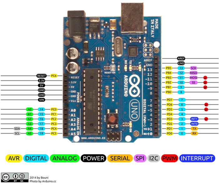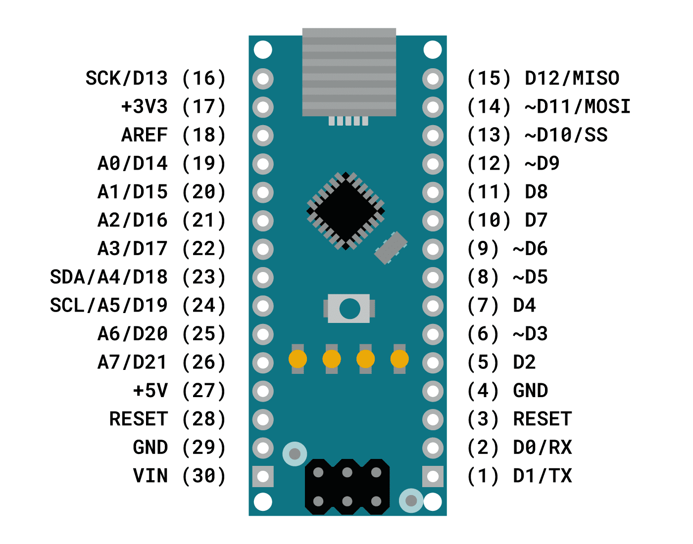

Arduino uno pinout drawing series#
Ex: adding a 10k resistor in series with the input pin permits input voltages as low as -10.5V or as high as +15.5V.


Since AVR microcontrollers (ex: the Atmel ATmega328) have internal clipping diodes (note that Atmel, mistakenly I believe, calls them "clamping diodes"), this can be done by simply adding a single resistor in series with the pin. If your input signal is digital, and you don't need to take scaled analog readings, another technique is to clip (cut the top off of) the input voltage, rather than scale it. This scales the input voltage to allow for analog or digital readings of voltages otherwise outside the allowed range. If it is outside these limits, you can bring down the voltage using a voltage divider.

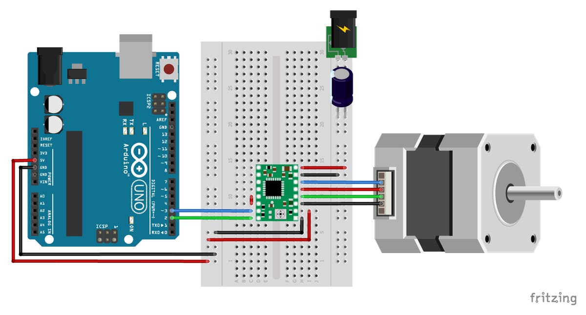
Caution: before touching any electro-static discharge (ESD) sensitive parts on the Arduino (which is pretty much all of the Arduino), touch the metal part of the USB plug first to ground yourself out to the board and safely discharge any static voltage you have built up. In the picture below, the black device at the left side of the Arduino, circled in yellow, is the voltage regulator. If it feels too hot to comfortably touch, you need to use a voltage source within the recommended limits in order to reduce heat buildup. Feel the voltage regulator with your finger. Sustained voltage leves above 12V will cause additional heating on the linear voltage regulator of the Arduino, which could cause it to overheat.Below 7V may cause the 5V levels on the board to waver, fluctuate, or sag, causing board instability and less accurate analog readings when using analogRead().Absolute voltage limits for powering the Arduino: 6~20V.These input voltages can be sustained indefinitely.Recommended input voltage limits: 7~12V.When powering the Arduino via the power jack or VIN and GND pins, it has the following input voltage limitations: Input power: to power the Arduino, you either plug it in to a USB port, or you input a voltage source to it either its 2.1mm x 5.5mm DC power jack (if present, such as on the Uno) or via jumpers going to its "VIN" and "GND" pins (which are on all Arduinos that I've seen).Power Limitations of the Arduino Uno & Nano: Read my article here for more info: Quick Tip: Arduino Input/Output (I/O) Pin Over-Voltage Protection Using a *Single* Resistor! A 100k resistor allows DC input voltages from -100.5V to +105.5V. Ex: a 10k resistor provides voltage enough protection to allow input voltages between -10.5V and +15.5V. Note 1: simply by adding a resistor in series with an I/O pin, you get increased input voltage protection for that pin. Sum of all input/output pins combined (but NOT including the "5V" pin): 200mA.5V pin: same as above: 500mA or 500mA~1A.With external battery or power supply: total of 500mA~1A (see below for specifics).Input/Output (I/O) pins: -0.5V to +5.5V (the actual max is "Vcc + 0.5V," which for a 5V Arduino, is +5.5V) ( Note 1).References will be included at the end, and references for particular data are denoted by square braces with the reference number, such as this: "." Following my references and methodology, you can use the same techniques to figure out the limits of your particular board, in case you're not using an Uno or Nano. Here, I will attempt to succinctly and accurately describe the power limitations of the standard Arduino boards, such as the Uno and Nano. In either case, it's important to understand the limitations of your Arduino, its input/output pins, and its voltage regulators. Larger servos and motors like these have the potential to push the Arduino past its max current limits, potentially causing it to reset itself and cause unusual errors while running, or possibly even damage the Arduino (I should note that most linear voltage regulators have an over-temperature auto-cutoff feature, however, so damage is unlikely). In using Arduino and designing my circuits for it, I have often-times asked myself the question, "What are the power/current/voltage limitations of the Arduino?" "Will I risk damaging it?" In the image above, for instance, a large servo is being powered by the voltage regulator right on the Arduino development board. (image above is from this Adafruit tutorial here)


 0 kommentar(er)
